For over a century, the manufacturing world has relied on traditional electroplating to protect and beautify metal parts. From the gleaming chrome bumper on a classic car to the corrosion-resistant fasteners inside an airplane wing, electroplating has been the go-to solution for durability and aesthetics.
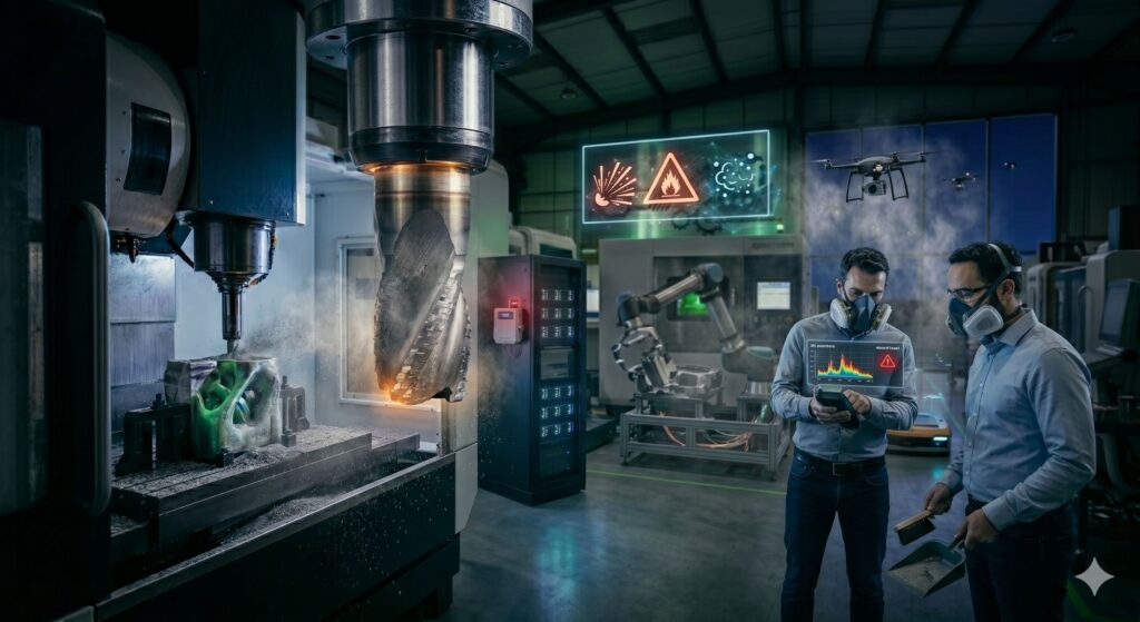
However, behind the brilliant shine of traditional electroplating lies a dark environmental reality. The process heavily depends on toxic chemical baths filled with hexavalent chromium, cyanides, and volatile heavy metals.
These chemicals present massive disposal challenges, pollute waterways, and pose severe health risks to factory workers.
As global environmental regulations tighten and consumers demand eco-conscious products, the manufacturing sector is facing a defining moment. The industry is rapidly shifting away from legacy chemical plating and turning to a new generation of Green Surface Treatments.
1. The Toxic Legacy of Traditional Electroplating
To understand why the industry is desperate for alternatives, we have to look into the traditional plating tank. Standard electroplating works by submerging a metal component into a liquid chemical solution (electrolyte) and passing an electrical current through it, causing dissolved metal ions to coat the part.
The most notorious villain in this process is Hexavalent Chromium—the chemical made famous by the environmental activist Erin Brockovich. It is a known human carcinogen that can cause severe respiratory damage, skin ulcers, and long-term organ failure.
Furthermore, traditional electroplating generates millions of gallons of toxic sludge annually. Disposing of this hazardous waste requires energy-intensive chemical treatments, and any accidental leak can devastate local ecosystems for generations. It is a linear, dirty process that simply does not fit into a sustainable future.
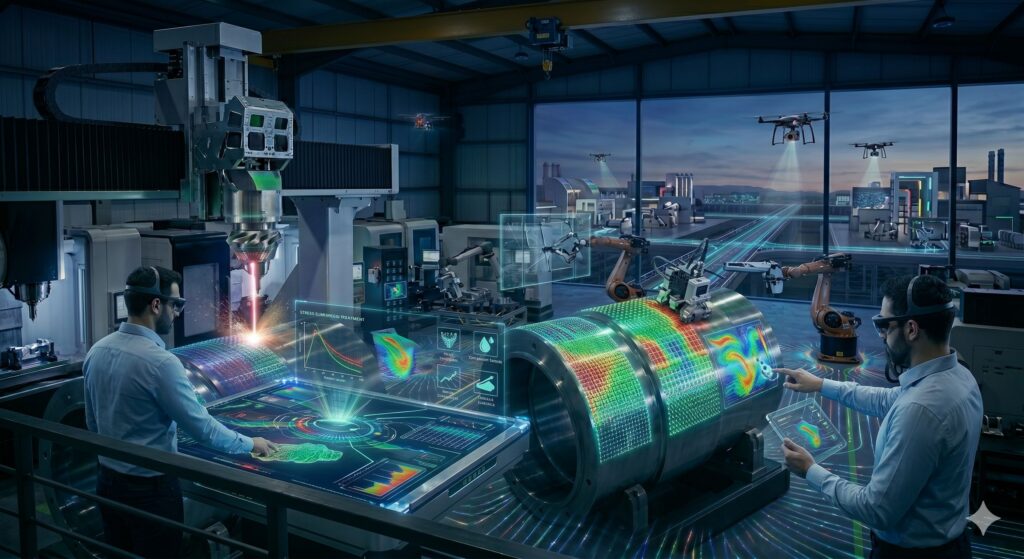
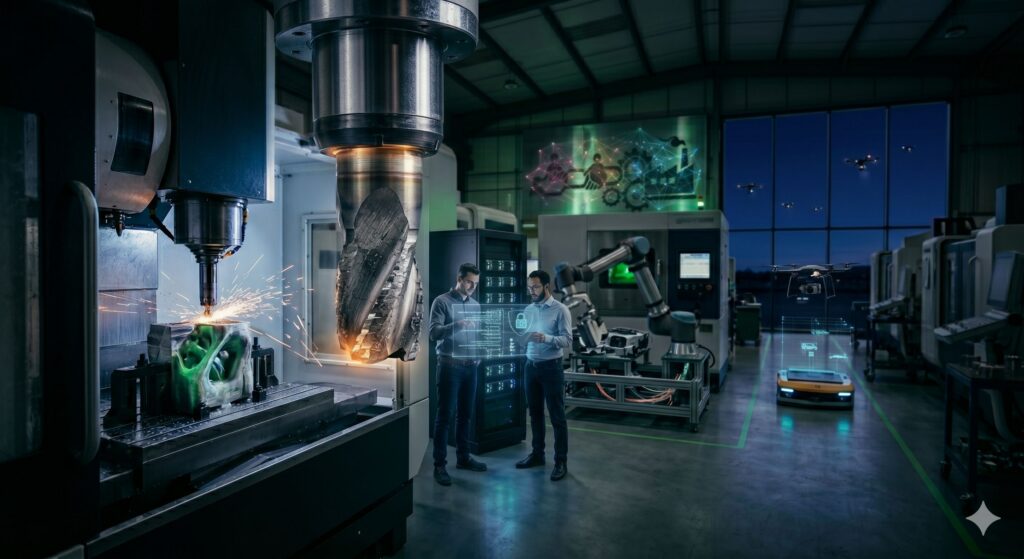
2. The Clean Revolution: Physical Vapor Deposition (PVD)
The leading contender to replace traditional electroplating is Physical Vapor Deposition (PVD). Instead of using toxic liquid chemical baths, PVD takes place inside a sealed, high-vacuum chamber.
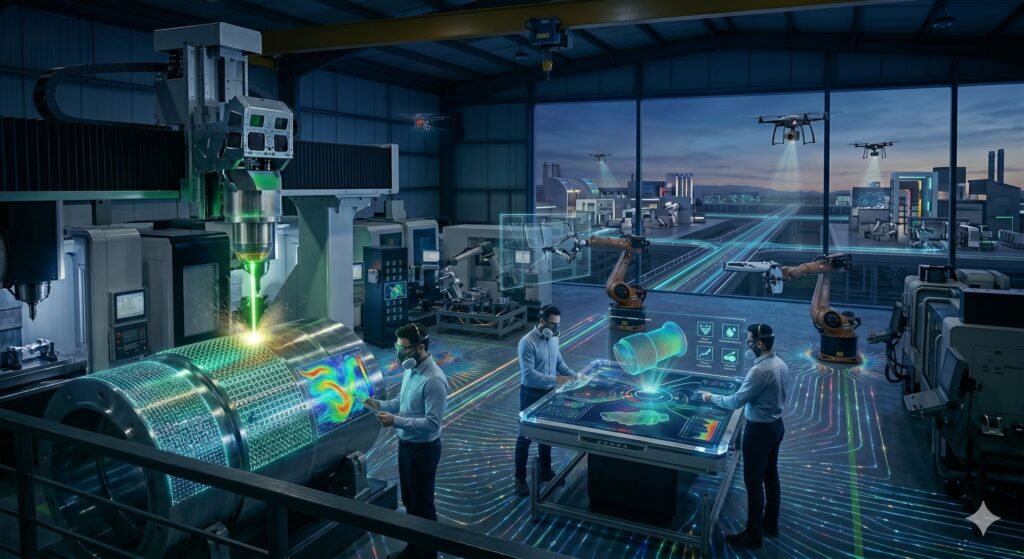
Inside the chamber, a solid coating material (such as titanium, chrome, or aluminum) is bombarded by an energy source like an electrical arc or a laser.
This causes the solid metal to instantly vaporize into a microscopic cloud of atoms. These vaporized atoms travel through the vacuum and condense onto the surface of the workpiece, creating a highly uniform, ultra-thin protective layer.
Why PVD is Green:
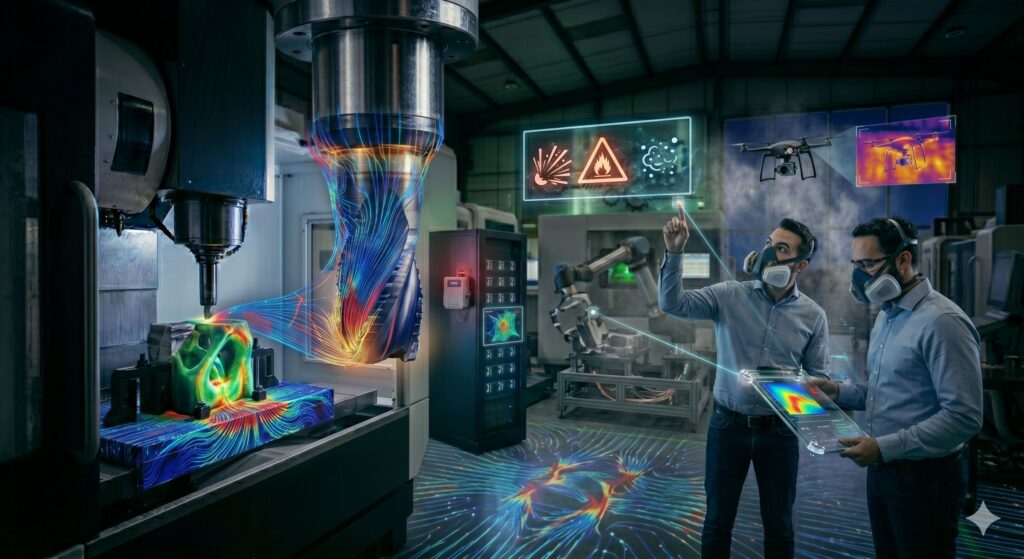
- Zero Hazardous Waste: PVD produces no toxic sludge, uses no harmful acids or cyanides, and releases zero chemical emissions into the atmosphere.
- Worker Safety: Because the entire process happens inside a fully sealed vacuum chamber, operators are completely shielded from chemical exposure.
- Infinite Material Options: PVD can apply coatings onto a vast array of substrates, including metals, ceramics, composites, and even eco-plastics.
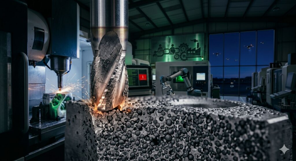
Beyond being green, PVD coatings are often significantly harder and more wear-resistant than traditional electroplated layers, proving that sustainability does not require a sacrifice in performance.
3. Harnessing Nature: Bio-Based and Eco-Friendly Chemical Alternatives
When a liquid process is absolutely necessary—such as coating the inside of complex, hollow geometries where line-of-sight PVD lasers cannot reach—manufacturers are replacing toxic electrolytes with green chemistry.
Trivalent Chromium Plating
Instead of using hazardous hexavalent chromium, modern shops are transitioning to Trivalent Chromium. Trivalent chrome is significantly less toxic, naturally occurring, and does not pose the same aggressive health risks to human workers. While the chemistry requires more precise control on the factory floor, it delivers a nearly identical, high-gloss finish.
Plant-Derived Bio-Coatings
In applications like temporary rust prevention or light industrial coatings, petroleum-based oils and solvents are being replaced by bio-based solutions derived from renewable agricultural resources like soybean, corn, and rapeseed oils. These natural formulations are completely biodegradable, non-toxic, and break down harmlessly if spilled.
4. Anodizing: The Clean Alternative for Aluminum
For industries working heavily with aluminum, like consumer electronics and aerospace, traditional plating is being completely phased out in favor of Anodizing.
Anodizing is an electrochemical process, but unlike electroplating which puts a foreign metal layer on top of the part, anodizing changes the structure of the aluminum itself. The part is immersed in an acid electrolyte bath, and an electric current is applied.
This forces the aluminum to oxidize, creating a highly controlled, porous, and ultra-hard top layer of aluminum oxide.
Because the process simply accelerates a natural oxidation process, the chemicals used (typically sulfuric or organic acids) are significantly easier to neutralize and recycle than heavy-metal plating baths.
Furthermore, the porous oxide layer can be colored using organic, water-based dyes, creating vibrant, premium finishes (like the colorful bodies of modern smartphones and laptops) with a fraction of the environmental impact.
The Bottom Line: A Shiny Future Without the Grime
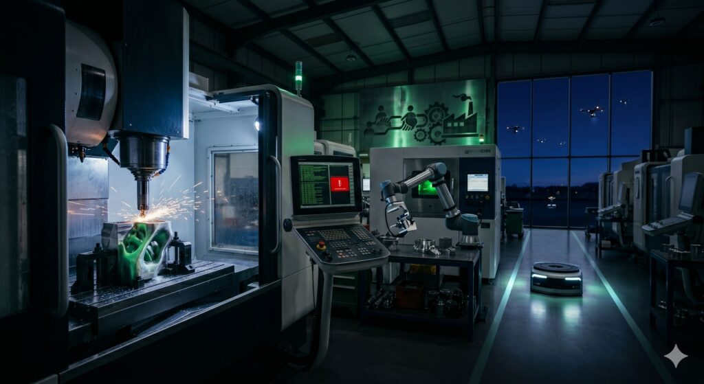
The transition from traditional electroplating to green surface treatments represents a massive leap forward for sustainable manufacturing. It shatters the old paradigm that a shiny, durable product must come at the expense of environmental destruction and worker health.
By investing in vacuum-based technologies like PVD, upgrading to safer trivalent chemistries, and embracing natural bio-coatings, modern factories are cleaning up their act. The future of manufacturing is undeniably bright—and it doesn’t require toxic chemicals to shine.