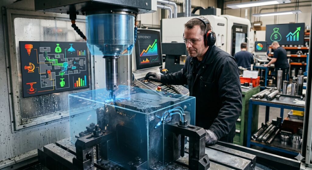
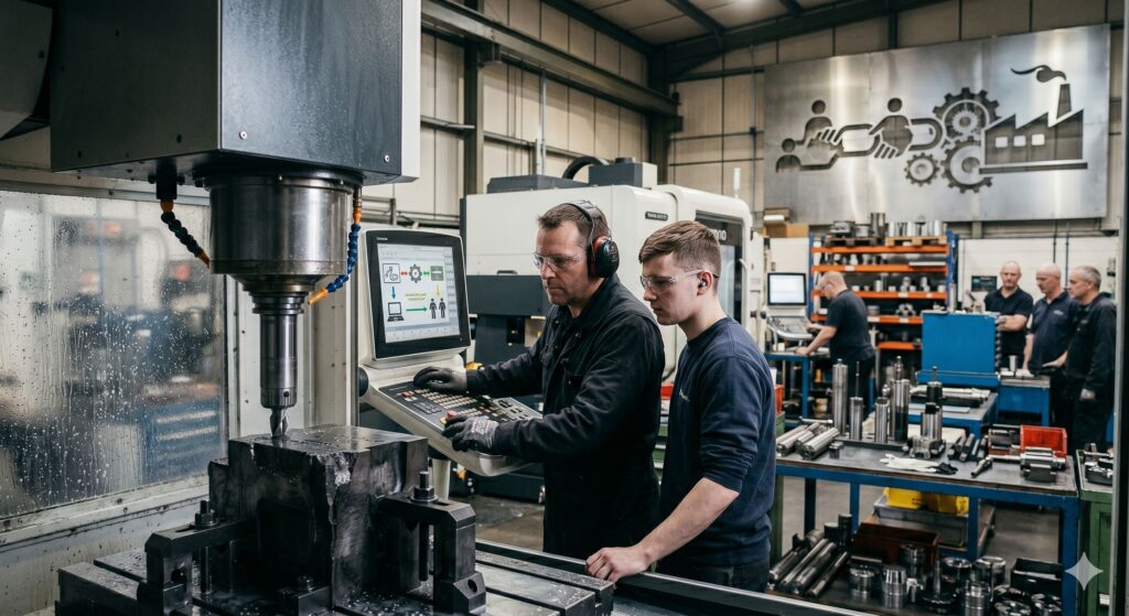
Walk through the floor of any manufacturing plant, power utility, or precision machine shop today, and you will notice a striking trend: some of the most critical, complex machines are being run by operators who are rapidly approaching retirement age.
Across the globe, industrial sectors are facing a quiet demographic crisis.
As the “Baby Boomer” generation exits the workforce, they take with them something far more valuable than hours logged—they take decades of unwritten, intuitive, and highly specialized technical expertise.
This intersection of an aging workforce and the struggle for knowledge retention is one of the biggest operational risks facing modern industry. But it also presents an incredible opportunity to reinvent how we train, document, and pass the torch to the next generation.
1. The Hidden Cost of the “Tribal Knowledge” Gap
Every company has it: Tribal Knowledge. This is the information that doesn’t exist in any manual, standard operating procedure (SOP), or onboarding video.
- It’s knowing exactly how much a specific lever needs to be nudged when the ambient shop temperature changes.
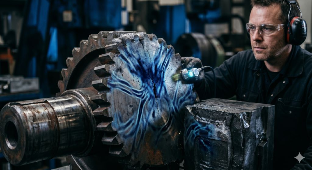
- It’s knowing the “heartbeat” sound of an industrial compressor right before it’s about to fail.
- It’s the mental catalog of how a custom system was cobbled together twenty years ago.
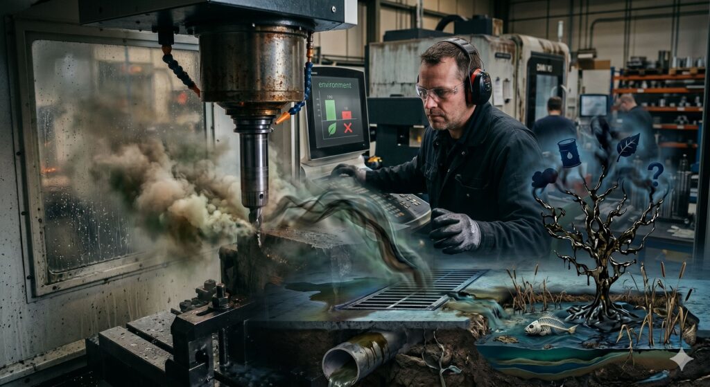
When an experienced technician walks out the door for retirement, that tribal knowledge walks out with them. If it hasn’t been captured, the company suffers from decreased efficiency, sudden downtime, costly trial-and-error troubleshooting, and a massive safety risk as younger, less experienced workers try to fill the void blindly.
2. Why the Generational Handover is Stalling
Passing down technical skills should be natural, but several modern hurdles are making this transition more difficult than in the past:
A. The Cultural Shift in Career Longevity
The incoming workforce approaches careers differently. While a retiring machinist might have stayed at one company for forty years, younger workers shift jobs more frequently. This makes long-term, slow-paced mentorship models harder to sustain.
B. The Technology Disconnect
Legacy systems often rely on analog skills, while younger technicians are digital natives. A veteran might troubleshoot by feel and sound, whereas a rookie expects an error code on a screen. Bridging this communication and methodology gap requires deliberate effort.
C. The “Busy-ness” Trap
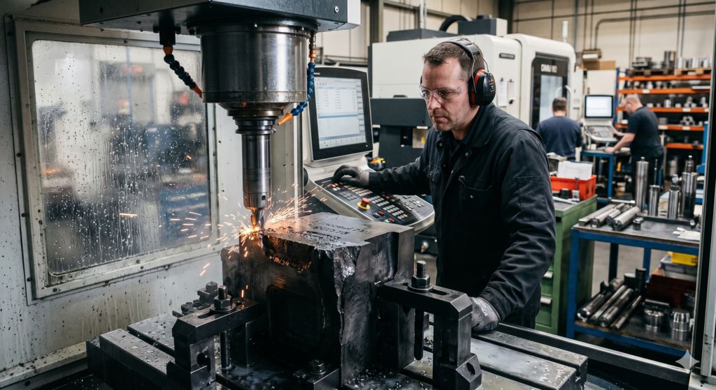
In hyper-optimized, lean manufacturing environments, veterans are often too busy hitting daily production quotas to sit down and teach. Without dedicated time carved out by management, mentorship becomes an afterthought.
3. Strategies for a Seamless Technical Succession
How do forward-thinking organizations stop the brain drain? They build structured systems that turn abstract experience into tangible, transferable company assets.
Capture the Core through Digital Mapping
Don’t wait for a veteran to give their two-week notice to ask how they do their job. Implement ongoing knowledge-capture programs. Use video documentation, wearable cameras (like smart glasses), and digital voice notes to document complex procedures from the veteran’s point of view while they are actively working.
Implement “Phased Retirement” and Mentorship Roles
Instead of a hard retirement date where a worker vanishes overnight, offer phased retirement. Allow senior technicians to transition into part-time roles where their primary KPI isn’t production output, but rather coaching and shadowing newer team members.
Reverse Mentoring: A Two-Way Street
Knowledge transfer shouldn’t be a one-way lecture. Pair a veteran worker with a tech-savvy younger worker. While the veteran teaches the nuances of the machinery, the younger worker can help the veteran adapt to new digital logging tools, tablets, or diagnostic software. This fosters mutual respect and accelerates learning for both sides.
Micro-Learning and Gamification
Younger generations absorb information differently. Massive, 300-page paper binders are rarely read. Instead, break down the veteran’s captured knowledge into short, bite-sized “micro-learning” videos or interactive troubleshooting trees accessible via a tablet right next to the machine.
The Bottom Line: Succession is an Investment, Not an Expense
An aging workforce isn’t a problem to be feared; it is a predictable cycle. The companies that will thrive in the coming decades are those that realize their greatest asset isn’t their physical machinery, but the collective intelligence of the people running them.
By treating technical succession as a strategic priority today, you don’t just protect your operational stability—you lay down a robust, high-tech foundation that makes your company incredibly attractive to the bright young talent of tomorrow.
Please get a free quote from Harry Yen hyen@unisontek.com.tw All of us are looking forward to your good news and invite you to visit our factory in Taiwan. Welcome to send any inquiry to us! Please watch presentation of our company on YouTube Link.